Description
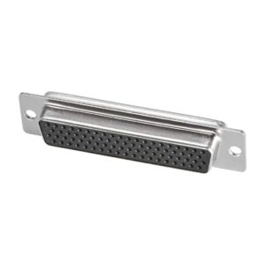
DB25 pin D sub Connector male Connector:
db25 rs232/db25 to usb/DB25 pin D sub Connector male/The DB-25 female connector is the parallel port connector for most personal computers. DB-25 for the first time with the original IBM personal computer (PC) with the use of long life. The female DB-25 has been widely used in the past for printer ports on PCs.
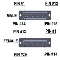
db25 rs232/db25 to usb/DB25 pin D sub Connector female/The DB25 connector is an analog socket.with 25 pins, from the D-Subminiatures (D-Sub) family. The prefix “D” represents the D-shape of the connector shell. The DB25 connector is mainly used in serial and parallel ports, allowing asynchronous data transmission according to the RS-232 standard (RS-232C). Note that there are DB9-DB25 adapters that easily convert a DB9 socket to DB25.
1. D sub male Connector WITH SOLDER CONTACTS.
The solder contacts have a cavity into which the stripped and tinned wire is inserted and then soldered.
2. DB25 male Connector D-SUB MINIATURE WITH INSULATION DISPLACEMENT CONTACTS (IDC).
The insulation displacement contacts (I.D.C.) are designed for automated assembly. A flat cable is pressed against the contacts, the rear of which is fork-shaped, which then pierce the insulation of all the wires simultaneously.
3. DB25 DSUB WITH CRIMPED CONTACTS
The crimp contacts are wired by inserting a stripped end of wire into a cavity at the back of the contact. The cavity is then crimped using a crimping tool. The contact is then inserted into the connector. Pins can be removed later with a tool inserted into the back of the connector. This “rear disconnect” is useful when the pins on the device are damaged.
4.PCB MOUNTED DSUB DB25 CONNECTOR
There are also two types of PCB mounted connectors, straight or right-angle termination styles. This type of connector has built-in solder tails for easy mounting on a PCB.