")


Description
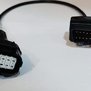
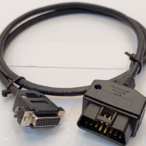
CANdapter Cable OBD-2 CAN-OBD-2 to DB9 Female Diagnostics Cable

DB9 Female cable, CAN DB9 Female Diagnostic, CANdapter makes simple the job of translating and extracting information from a CANBUS to a computer for processing and analysis. CANdapter communicates over a virtual serial port, making it an operating system independent and very simple to write programs and applications for.
Limitations
The adapter uses a USB FIFO to communicate with the computer. This limits the speed of the device due to the large amounts of data passing through a small channel. Therefore it is designed to be used most effectively for lower-speed automotive (500 Kbps) CANBUS baud rates, though it is rated for up to 1
Mbps. The device must be actively polled to prevent the FIFO from filling up. If the device is not actively polled, the FIFO will fill up, preventing the transmission of messages. Make sure that you poll the CANdapter while transmitting messages.
Features
- Low cost
- Up to 1Mbps baud rate
- Creates virtual serial port for easy access
- Supports extended identifiers
- Activity and error status LEDs
- Comes with a utility suite
- Sample code provided
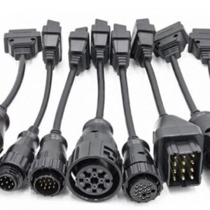
In OBD cable OBD Connector slim 16 pins obd2 male connector diagnostic connector.
What Is OBD Connectors/obd2 scanner :
In OBD Connector OBD-II is an improvement over OBD-I,obd2 male connector in both capability and standardization. The OBD2 Connector,obd2 male connector standard specifies the type of diagnostic connector and its pinout, the electrical signaling protocols available, and the messaging format. It also provides a candidate list of vehicle parameters to monitor along with how to encode the data for each. There is a pin in the connector that provides power for the scan tool from the vehicle battery, which eliminates the need to connect a scan tool to a power source separately.
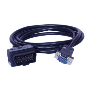
OBD-II diagnostic connector:
In total digi scan/pragathi solutions scan tool/J1962M to DB9F OBD Cable, Female OBD-II connectors on a car Female OBDII connectors pinout – it also has front view The OBDII,obd2 male connector specification provides for a standardized hardware interface—the female 16-pin (2×8) J1962 connectors. Unlike the OBD-I connector, which was sometimes found under the hood of the vehicle, the OBD-II connector is required to be within 2 feet (0.61 m) of the steering wheel (unless an exemption is applied for by the manufacturer, in which case it is still somewhere within reach of the driver).
SAE J1962 defines the pinout of the connector as:

The basic strategy for communicating with the CANdapter has 4
1) Opening the serial communication port: This can be accomplished with any number of libraries and utilities and will be specific to the programming language you are using. Once you have the serial communication port open, you can begin sending commands to the adapter.
2) Initializing the CANdapter: Before the CANdapter can communicate with the CANBUS, it must first be initialized. Specifically, the baud rate needs to be set, along with other options such as timestamps, filters, and masks. These must be set before the CANBUS channel is opened. Once you are finished sending the initialization commands to the CANdapter, send the O command to open the CANBUS port. At this point, you can no longer change the initial configuration. The CANBUS should now be open and active.
3) Issuing commands to the CAN adapter: At this point, the CAN adapter is live and ready to receive and respond to commands. Please see the command section for
a list of commands.
4) Closing the CANBUS: When you are finished, close the CANBUS channel by issuing the C command.